Single-byte data corruption from FT232H Hardware Limits #94
Comments
Designed for communication with SPI Flash memory chips.

Single-use or combinations of the existing methods are not efficient or functional for the use case of NOR/NAND flash chip reading and writing. It is essential that between reading and writing the Chip Select remains asserted (High) for the entire period. Usage of the `write` and `read` methods is therefore not possible in combination because each of them de-asserts CS at the end of the method. There is no need for that behavior to change though.

The `transfer` method is inefficient because it sends a command to the FT232H that not only allows Full-Duplex but actually REQUIRES it for a command to complete. This is due to the design of the MPSSE. If I use the same FT232H command and attempt to read more than I am writing, a timeout occurs. In other words, the FT232H only allows communication at all during a Full-duplex command when there is data to be handled in Full-duplex, the amount you read MUST BE equal to the amount you write.

For example, an SPI read of a NOR flash chip: After instructing the FT232H to open the connection to the flash chip, you write the command to the slave as 1 byte, then the address as 3 bytes and the chip responds AFTER the write, not DURING, for as long as CS is asserted. In order to read only 1 of the 64 blocks of a 4 MB flash chip using the `transfer` method, I would have to append 65,532 zeros to the array that I am writing to the chip to keep the connection alive for each iteration of the loop, which is mandated both by the slave (NOR Flash) with CS, and by the master (FT232H) with the full-duplex command. Again, half-duplex read then write is a very simple matter, as with any SPI slave, that would be treated as two separate commands, `read` and then `write`. But on many SPI slaves, half-duplex write then read is almost always in the same instruction, where CS assertion must not be interrupted between commands of the master (FT232H), and this is a very popular implementation.

I have also designed this method to solve the issue adafruit#94 that I posted


For a while, I thought it should work with a single write command and two poll reads
...not true...


in parallel order, double read still doesnt fix it:
```
spi._ft232h._write(str(bytearray((commandR, len_lowR, len_highR))))
spi._ft232h._write(str(bytearray((commandR, len_lowR, len_highR))))
payload1 = spi._ft232h._poll_read(lengthR)
payload2 = spi._ft232h._poll_read(lengthR)
```

but in series order, double read does give clean output:
```
spi._ft232h._write(str(bytearray((commandR, len_lowR, len_highR))))
payload1 = spi._ft232h._poll_read(lengthR)
spi._ft232h._write(str(bytearray((commandR, len_lowR, len_highR))))
payload2 = spi._ft232h._poll_read(lengthR)
```


This is tested both in situations where the expected output is all ff, the expected output is all 00, or the expected output is real life data, confirmed with CRC32.

My take on this is basically sacrificing a little more python environment memory, to save the chips buffer from suffering. I am convinced that the problem is NOT with the poll_read function.
I am not sure if it is just my chip with this problem or many more, but this surely prevents it from appearing during heavy use, at practically any frequency. I have tried setting my clock as low as 1 MHz.


Therefore I propose this method, bulkread (I can't think of a better name, maybe readblock) with the following features...

  - both the array to write and the length to read back are optional (one or the other), configurable, and with defaults
  - allows a read up to the limit of the FT232H capabilities, both hard limit in the datasheet (64 KB) by ensuring input is within the range...
  - and soft limit handling from data corruption issue observed in my real life testing by simply performing two separate poll reads (see adafruit#94)
  - Warning the user about the data length limits
  - Deasserting CS is the VERY LAST action sent to the FT232H
  - the buffer flush command (0x87) is not used, in my testing, it makes no difference, less talking to the master means more talking to the slave.
  - a very simple mode setting, to allow writing only with the same method, not having to change methods by setting readmode to 0
  - all math is moved to the top, before anything is pushed to the device


Similar logic should be applied to every other method in the library, to inform the user before errors occur, and prevent errors due to (most likely) hardware defects.


@ladyada @tdicola Please help me out with the logger.debug line...I'm not sure about the syntax or purpose or usage of it
Applying fixes described here:
adafruit#94
adafruit#95

In order to:
Prevent a data stream larger than 64 KB from passing per command and warn the user
Fix the weird data corruption error that may or may not occur from full hardware limit length reads
Designed for communication with SPI Flash memory chips.

Single-use or combinations of the existing methods are not efficient or functional for the use case of NOR/NAND flash chip reading and writing. It is essential that between reading and writing the Chip Select remains asserted (High) for the entire period. Usage of the `write` and `read` methods is therefore not possible in combination because each of them de-asserts CS at the end of the method. There is no need for that behavior to change though.

The `transfer` method is inefficient because it sends a command to the FT232H that not only allows Full-Duplex but actually REQUIRES it for a command to complete. This is due to the design of the MPSSE. If I use the same FT232H command and attempt to read more than I am writing, a timeout occurs. In other words, the FT232H only allows communication at all during a Full-duplex command when there is data to be handled in Full-duplex, the amount you read MUST BE equal to the amount you write.

For example, an SPI read of a NOR flash chip: After instructing the FT232H to open the connection to the flash chip, you write the command to the slave as 1 byte, then the address as 3 bytes and the chip responds AFTER the write, not DURING, for as long as CS is asserted. In order to read only 1 of the 64 blocks of a 4 MB flash chip using the `transfer` method, I would have to append 65,532 zeros to the array that I am writing to the chip to keep the connection alive for each iteration of the loop, which is mandated both by the slave (NOR Flash) with CS, and by the master (FT232H) with the full-duplex command. Again, half-duplex read then write is a very simple matter, as with any SPI slave, that would be treated as two separate commands, `read` and then `write`. But on many SPI slaves, half-duplex write then read is almost always in the same instruction, where CS assertion must not be interrupted between commands of the master (FT232H), and this is a very popular implementation.

I have also designed this method to solve the issue adafruit#94 that I posted


For a while, I thought it should work with a single write command and two poll reads
...not true...


in parallel order, double read still doesnt fix it:
```
spi._ft232h._write(str(bytearray((commandR, len_lowR, len_highR))))
spi._ft232h._write(str(bytearray((commandR, len_lowR, len_highR))))
payload1 = spi._ft232h._poll_read(lengthR)
payload2 = spi._ft232h._poll_read(lengthR)
```

but in series order, double read does give clean output:
```
spi._ft232h._write(str(bytearray((commandR, len_lowR, len_highR))))
payload1 = spi._ft232h._poll_read(lengthR)
spi._ft232h._write(str(bytearray((commandR, len_lowR, len_highR))))
payload2 = spi._ft232h._poll_read(lengthR)
```


This is tested both in situations where the expected output is all ff, the expected output is all 00, or the expected output is real life data, confirmed with CRC32.

My take on this is basically sacrificing a little more python environment memory, to save the chips buffer from suffering. I am convinced that the problem is NOT with the poll_read function.
I am not sure if it is just my chip with this problem or many more, but this surely prevents it from appearing during heavy use, at practically any frequency. I have tried setting my clock as low as 1 MHz.


Therefore I propose this method, bulkread (I can't think of a better name, maybe readblock) with the following features...

  - both the array to write and the length to read back are optional (one or the other), configurable, and with defaults
  - allows a read up to the limit of the FT232H capabilities, both hard limit in the datasheet (64 KB) by ensuring input is within the range...
  - and soft limit handling from data corruption issue observed in my real life testing by simply performing two separate poll reads (see adafruit#94)
  - Warning the user about the data length limits
  - Deasserting CS is the VERY LAST action sent to the FT232H
  - the buffer flush command (0x87) is not used, in my testing, it makes no difference, less talking to the master means more talking to the slave.
  - a very simple mode setting, to allow writing only with the same method, not having to change methods by setting readmode to 0
  - all math is moved to the top, before anything is pushed to the device


Similar logic should be applied to every other method in the library, to inform the user before errors occur, and prevent errors due to (most likely) hardware defects.


@ladyada @tdicola Please help me out with the logger.debug line...I'm not sure about the syntax or purpose or usage of it
|
Was fixed for SPI methods by #98 Edit: even though the poll_read function is not the direct cause, this is targeted on how that function is used |
|
Hi, I could initially not get it to work, and after much testing found out, that I needed to double the size of the writes by adding zeros. It turned out that the SPI It seems to be related to or done as part of this Issue and its pull requests - specifically #100. I don't completely understand the reason for always breaking all writes into two transactions, but is it possible the fix could be made less "heavy handed" and only do two writes when strictly necessary? Or could it be solved some other way? I do not think it is appropriate/intentional to break the Adafruit learning examples or timing sensitive SPI applications in general. So can I help in any way to fix this? |
|
Hi again @vestom, Yeah, these changes are all from me and I explained the reasoning pretty clearly above but didn't expect any consequences from it.... To summarize quickly for you, programming flash chips requires bit-perfect writing and reading. I experienced bit errors near the end of every read that was at the full limit of the chip (64 KB) until I made these changes and noticed that any read from length 1 to around 62 KB was always good. I have not been able to determine the cause though. My testing showed that after the changes that the methods are still consistent with the strict format of an SPI sequence by having completely clean reads and writes every time to and from a flash chip, at the very least, with the signal characteristics that the flash chips allow, which I would expect to also be strict. The write commands were changed in an almost identical way as the read commands, except for the if statements which might be introducing latency in your case, but I don't think that's the problem...I've never had issues with any of the commands after the changes, and this is for programming flash chips where I made sure to check for bit perfect writes and reads... It's worth noting that I used a pretty low frequency in most of my testing, but I never noticed anything getting worse whenever I went past 1 MHz. I'm going to look at this again soon with my own setup... So like you said, it all comes down to timing, but in this case the Neopixels have a weird non-SPI data method...and the script they wrote is actually using a whole byte of SPI to spoof a single bit of either a 33% duty cycle square wave or a 66% duty cycle square wave... see this: A couple of things to note: First, its a "self-clocking" signal with fixed-frequency. This greatly limits the configuration and performance requirements of the microcontroller. They say that "there’s nearly 25% “wiggle room” in the timing" (I think they mean the duty cycles) but it is possible that the chips I have been working with have a greater safety net, since they require a clock signal, and in the case of a real SPI serial connection, these small latencies are meaningless, but in your case, means all the difference. I guess what's really happening, is the clock signal lags consistently with the data signal, which allows it to not affect a true SPI sequence, which is allowed to have a variable frequency or pausing signal, as long as Chip Select remains high and the slave device will continue listening. The frequency that the WS2812 actually uses is 800 KHz (1 / 1.25 microseconds). In order to spoof this interface using SPI in the way they designed, we would want to oversample by a ratio of 8 to 1 or bytes to bits. However, they tell you to set it to 6 MHz instead of 6.4 MHz which shouldn't give you correct results at all...that might help but doesn't explain why it works with 6 MHz. Maybe a 6 percent different doesn't mean anything. Maybe the FT232H is incapable of producing 6.4 MHz and would default to 6 anyway. You can also try exactly half of that frequency, 3.2 MHz, as it's supposedly backward compatible with its predecessor chip that runs at 400 KHz. Another thing that concerns me about the script they supply is that there is a write cycle for every single pixel set (unless you're not using that part of the supplied code). Continuous writing of 3 bytes might just be too fast for the actual data buffering to catch up. Does the pattern work? What about taking You might not even want to use the SPI method since its not actually SPI...There is a pull request for 1-wire support that you might want to test out at #58 BTW there is a separate library dedicated to the Neopixels. Maybe that code can be ported from C++ to Python If none of this helps we can introduce a simple mode switch for write() like there is in bulkread()... |
|
Yes, WS2812 is not strictly SPI, but I think it is a shame to preclude other "shift register like" uses (e.g. PWM generation), and it seems unnecessary to always break writes into two, if it can be limited to corner cases. It sounds like it should be simple to only do two writes if the data size is bigger than 62k, instead of introducing modes and whatnot. I have my WS2812 LEDs working now, but that was really just fooling around to evaluate this library for some other project. I am also testing the pyftdi library. |
|
Let's assume someone wanted to light as many LEDs as they could with the FT232H using this oversampling style, which I believe would be 341. They would run into the same problem, and if we had the original write() method without breaking the writes into two, I assume one of the LEDs would be incorrect. Which case is better? Until we know for sure, the user can decide. We can also just make two different methods. I made the bulkread() method which didn't exist before I made these changes because the function was very different than read() (reads and writes in the same method). |
|
I do not question there is a problem with large writes that should be solved. However the current code is broken for even 1 LED, since it is applying a fix, where none is needed. And no amount of special modes or functions would make it work beyond the hardware limits anyway... However, you do not need to argue with me. I have moved on... |
|
hiya thank you for the issue. we're going to be deprecating this library in favor of our python3 Blinka library which has support for almost 200 different drivers, and a wide variety of linux computers as well as ft232h |
FTDI is very clear with the limits of the MPSSE commands in the following datasheet:
https://www.ftdichip.com/Support/Documents/AppNotes/AN_108_Command_Processor_for_MPSSE_and_MCU_Host_Bus_Emulation_Modes.pdf
For every command you basically see this:
or
However, I discovered that the number for the maximum bytes is a bit of an overstatement. It is definitely not due to the library on this repo, but it may be because of libFTDI or the USB library used...It may even be due to a defect on my specific chip or in the design of the breakout schematic and components used, not sure...
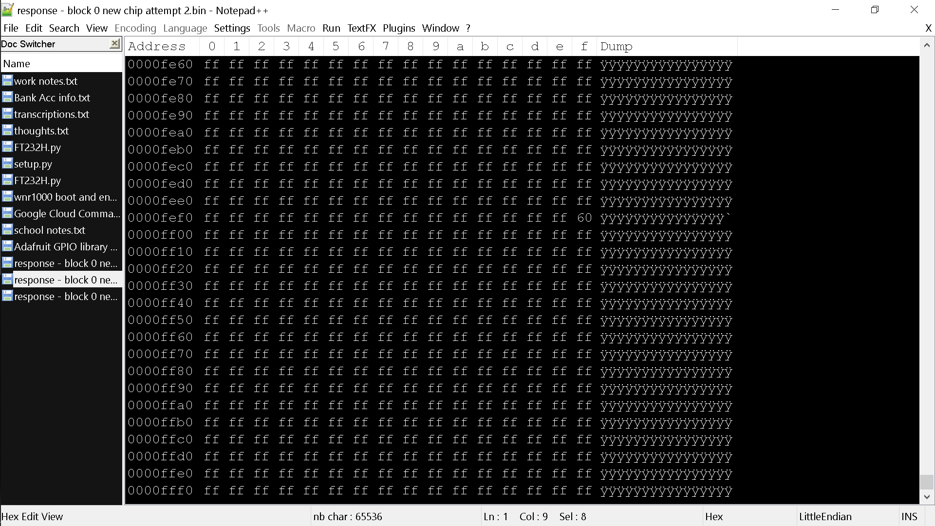
I have made a script to read from an SPI NOR Flash chip to completion, but because of this hardware limit of 64 KB, it uses for loops to read 1 block of the NOR memory at a time. I soon realized that I was getting data error or corruption in only ONE address per block, and it was the SAME address almost every time. I realized this by comparing CRC32 and then using VBinDiff.exe to see where and why.
For every block of the chip, the value for 0x__FFEF was 0x60
I only experienced this data corruption in one other address once, out of the probably 20-30 times I witnessed it.
It is worth noting that this occurs even when there is no chip being read. I could have the FT232H not even wired to anything, not even connected to a breadboard and I get the same thing at the same address, where we should be expecting every byte to be 0xFF due to there being no device. I am using a very premium USB cable from Anker
Here is a screenshot where we expect all 0xFF
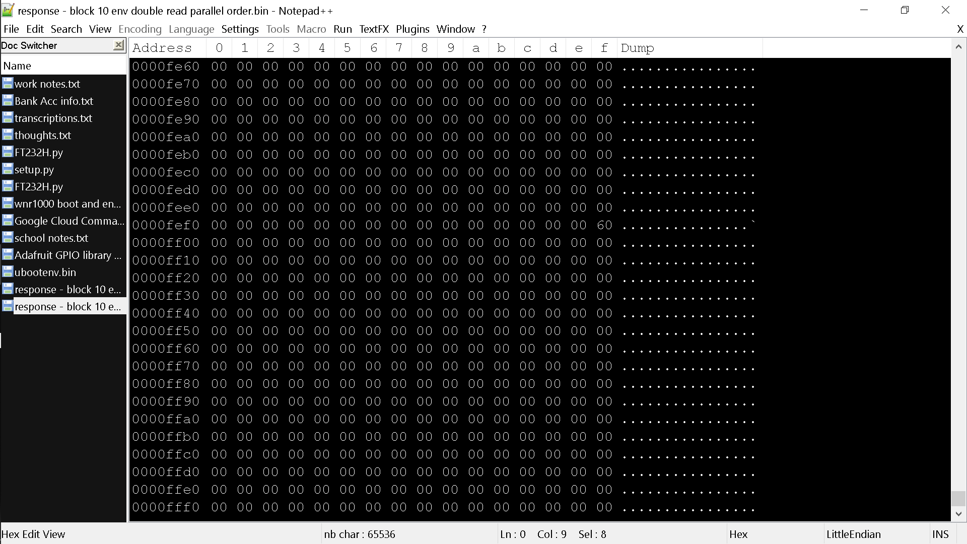
Here is a screenshot where we expect all 0x00
One of the things I tried was to further split the read commands into two and perform them twice per loop. This fixed the problem for me immediately. Since then I have been working on how to include this into the methods themselves rather than just my own script. I believe this is a good safety measure for accuracy even if it is only my board with the problem...
Posting a pull request to solve it soon, at least for SPI commands...
While porting it into the method. I see that doing a double poll read "in parallel" rendered the same result, but a double poll read "in series" gives the correct result. I'll explain that later in the pull request.
The text was updated successfully, but these errors were encountered: