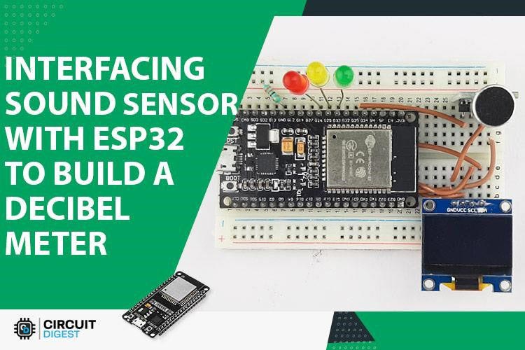
This project demonstrates how to interface the KY-038 sound sensor module with an ESP32 microcontroller to create a sound-activated control system. The KY-038 is a microphone sound sensor that can detect sound intensity and trigger actions based on ambient noise levels, making it ideal for voice-activated switches, clap switches, and sound-responsive automation systems.
Full tutorial and detailed explanation: Interface KY-038 Sound Sensor with ESP32 - Circuit Digest
- Real-time Sound Detection: Monitors ambient sound levels continuously
- Dual Output Modes: Digital (DO) and Analog (AO) outputs for flexible implementation
- Adjustable Sensitivity: Built-in potentiometer for threshold adjustment
- LED Indicator: Visual feedback when sound is detected
- Low Power Consumption: Efficient operation suitable for battery-powered projects
- Easy Integration: Simple interfacing with ESP32 GPIO pins
- ESP32 Development Board (ESP32-DevKitC or similar)
- KY-038 Sound Sensor Module
- LED (optional, for visual indication)
- 220Ω Resistor (for LED)
- Breadboard
- Jumper Wires
- USB Cable (for programming and power)
- Operating Voltage: 3.3V - 5V
- Output: Digital (DO) and Analog (AO)
- Detection Range: Adjustable via potentiometer
- Microphone Type: Electret condenser microphone
- PCB Size: 32mm x 17mm
| KY-038 Pin | ESP32 Pin | Description |
|---|---|---|
| VCC | 3.3V | Power Supply |
| GND | GND | Ground |
| DO | GPIO 4 | Digital Output |
| AO | GPIO 34 | Analog Output (ADC1_CH6) |
| Component | ESP32 Pin |
|---|---|
| LED (+) via 220Ω | GPIO 2 |
| LED (-) | GND |
- Arduino IDE (version 1.8.x or later)
- ESP32 Board Package installed in Arduino IDE
- USB to UART Driver (CP210x or CH340)
- Install Arduino IDE from arduino.cc
- Add ESP32 board support:
- Go to File → Preferences
- Add to Additional Board Manager URLs:
https://raw.githubusercontent.com/espressif/arduino-esp32/gh-pages/package_esp32_index.json - Go to Tools → Board → Board Manager
- Search for "ESP32" and install
// Define pins
#define SOUND_SENSOR_DO 4  // Digital output
#define LED_PIN 2          // Built-in LED

void setup() {
  Serial.begin(115200);
  pinMode(SOUND_SENSOR_DO, INPUT);
  pinMode(LED_PIN, OUTPUT);
  Serial.println("Sound Sensor Initialized");
}

void loop() {
  int soundDetected = digitalRead(SOUND_SENSOR_DO);

  if (soundDetected == LOW) {  // Sound detected (active LOW)
    digitalWrite(LED_PIN, HIGH);
    Serial.println("Sound Detected!");
  } else {
    digitalWrite(LED_PIN, LOW);
  }

  delay(100);
}// Define pins
#define SOUND_SENSOR_AO 34 // Analog output (ADC)
#define LED_PIN 2 // Built-in LED
#define THRESHOLD 2000 // Adjust based on your environment
void setup() {
Serial.begin(115200);
pinMode(LED_PIN, OUTPUT);
Serial.println("Sound Intensity Monitor Started");
}
void loop() {
int soundLevel = analogRead(SOUND_SENSOR_AO);
Serial.print("Sound Level: ");
Serial.println(soundLevel);
if (soundLevel > THRESHOLD) {
digitalWrite(LED_PIN, HIGH);
Serial.println("Loud sound detected!");
} else {
digitalWrite(LED_PIN, LOW);
}
delay(100);
}- Connect the KY-038 module to ESP32 according to the pin connections table
- Connect the optional LED with resistor to GPIO 2
- Double-check all connections before powering up
- Power up the circuit
- Locate the potentiometer on the KY-038 module
- Turn the potentiometer clockwise to increase sensitivity
- Turn counter-clockwise to decrease sensitivity
- Adjust until the LED on the module lights up at desired sound levels
- Open Arduino IDE
- Select the correct board: Tools → Board → ESP32 Dev Module
- Select the correct port: Tools → Port → (your COM port)
- Copy and paste the code
- Click Upload button
- Open Serial Monitor (115200 baud) to view output
- Make sounds near the sensor (clap, talk, play music)
- Observe the LED and Serial Monitor output
- Adjust sensitivity if needed using the onboard potentiometer
- Voice-Activated Switches: Control lights or appliances with claps or voice
- Security Systems: Detect glass breaking or unusual sounds
- Noise Monitoring: Environmental noise level detection
- Interactive Art: Sound-responsive LED displays
- Smart Home Automation: Integrate with existing home automation systems
- Baby Monitor: Alert system for crying detection
- Music Visualization: Create sound-reactive displays
| Issue | Solution |
|---|---|
| No response from sensor | Check power connections (VCC and GND) |
| Always detecting sound | Decrease sensitivity using potentiometer |
| Never detecting sound | Increase sensitivity or check DO/AO connections |
| Erratic readings | Add small delay in loop, check for loose connections |
| ESP32 won't program | Hold BOOT button while uploading |
- Provides HIGH/LOW signal based on threshold
- Threshold adjusted via onboard potentiometer
- Good for simple on/off applications
- Provides variable voltage based on sound intensity
- ESP32 ADC reads values 0-4095
- Allows for graduated response and fine control
- Power LED: Lights when module is powered
- Status LED: Lights when sound exceeds threshold
Add relay module to control high-power devices:
#define RELAY_PIN 5

void setup() {
  pinMode(RELAY_PIN, OUTPUT);
  // ... other setup code
}

void loop() {
  if (soundDetected == LOW) {
    digitalWrite(RELAY_PIN, HIGH);  // Turn on device
    delay(5000);  // Keep on for 5 seconds
    digitalWrite(RELAY_PIN, LOW);
  }
}Use multiple KY-038 modules for directional sound detection or room coverage.
This project is open-source and available for educational and commercial use.
Contributions, issues, and feature requests are welcome! Feel free to check issues page.
Your Name - Your Contact Information
- Circuit Digest for the comprehensive tutorial
- ESP32 community for support and libraries
- Arduino community for the development platform
⭐ If you found this project helpful, please star it!
📧 For questions or suggestions, feel free to open an issue.
